Now that you’ve purchased heavy shop tools, you can make them mobile with a mobile tool base. The function of a mobile tool base is to allow your heavy shop tool to gain mobility so you can move it where you need it be. In most cases users wheel out their shop tool to use it and then wheel it near the wall for storage when they’re done. This helps you store your tool when not in use and to move it to a more convenient location for use. Mobile tool bases have casters that allow them to move about and offer a way to lock down the tool so it stays put to operate the tool. In this article I’m going to show you how to make a mobile tool base of your own instead of purchasing those expensive models you see online and hopefully you save yourself a bit of cash and have fun doing so along the way.
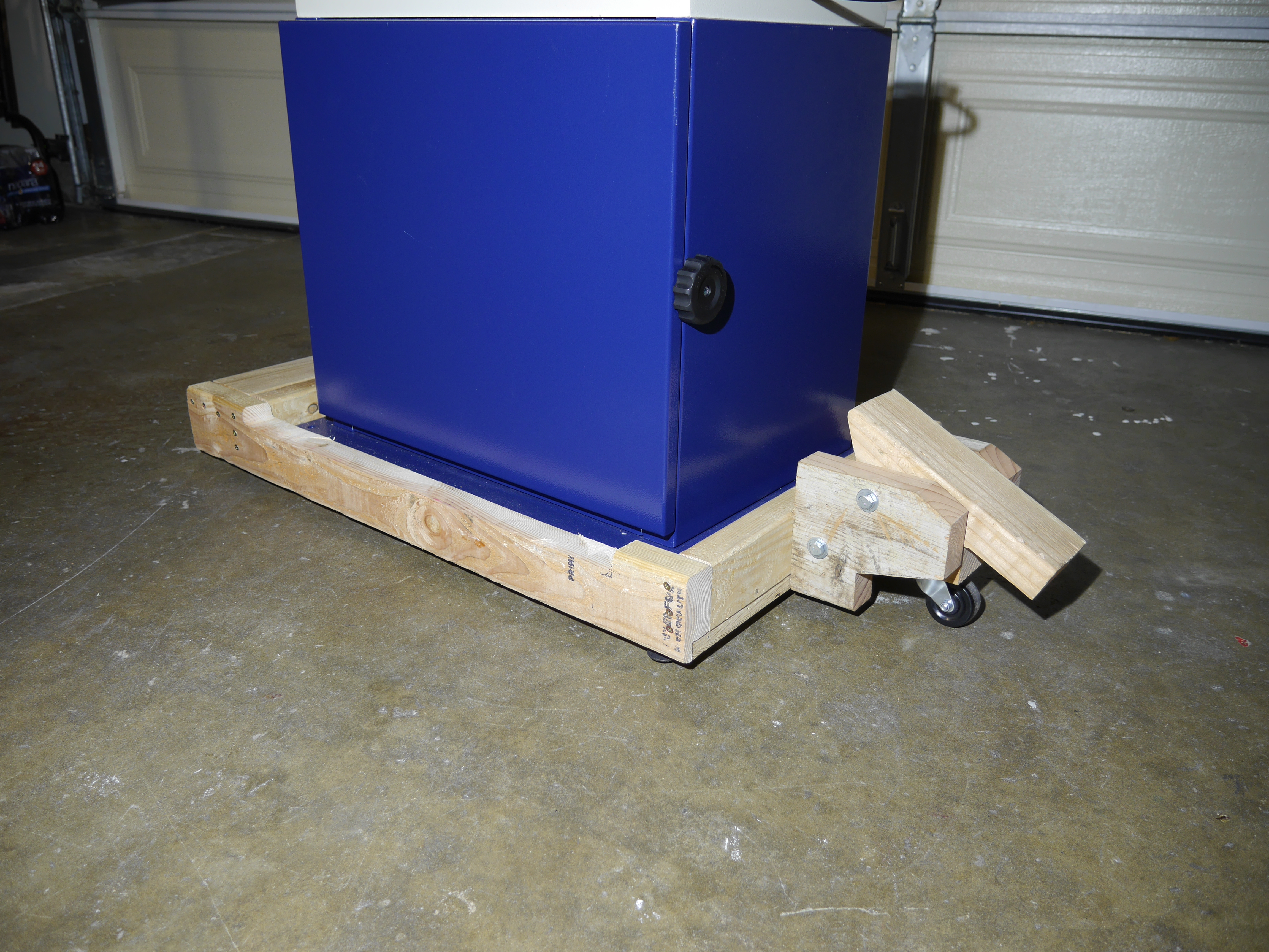 Before we get down to it, I’m going to give you a little bit of info on my version of the mobile tool base. This is a 3 wheeled base made with 2x lumber and plywood and features a foot activated lift mechanism. It’s nothing fancy but yet it’s not repulsive either. It rides on 2 fixed casters at one end with 1 rotating 360 degree castor on the opposite end to be able to turn as you move it around. I also incorporated 2 leveling feet on the side of the lifting mechanism so that you can keep your tool level when it is in use. The foot activated lifting mechanism is based on the design of metal foot activated foot levers.
Materials needed:
- 2×4 lumber (2 pieces @ 8ft length based on a shop tool with 30″x30″ base – more pieces if building a larger base)
- 2×6 lumber (minimum length needed 12-1/2″)
- 4×6 lumber (minimum length needed 9-1/8″)
- Optionally, you can use a 4×4 instead of a 4×6. There’s really no need to use 4×6 lumber for this project.
- I know in the video I mentioned to use a 4×6 for the foot lever however a 4×6 is unnecessary for the project and all you need is a 4×4 instead.
- Optionally, you can use a 4×4 instead of a 4×6. There’s really no need to use 4×6 lumber for this project.
- 3/4″ plywood (approximately 32″ L x 13″ W minimum based on a shop tool with 30″x30″ base -longer length if tool has a deeper base)
- 2″ heavy duty fixed casters (2 pieces)
- 2″ heavy duty rotating caster (1 piece)
- sheet metal – 26 gauge (will need enough to make one 3-1/4″x4-1/2″ and one 3-1/4″x7-1/2″ pieces)
- 8″ long 5/16″ course thread hex bolt (2 pieces)
- 5/16″ washers (12 pieces)
- 5/16″ lock nuts (2 pieces)
- 3-1/2″ long 1/4″ lag screws (4 pieces)
- 1/4″ copper pipe (minium 15″ length needed)
- 3″ #8 gold screws (18 pieces)
- 2″ #8 gold screws (amount needed varies)
- 1″ long 1/4″ lag screws (12 pieces)
- 5/16″-18 x 3/8″ T-Nuts (2 pieces)
- 5/16″-18 x 1-1/2″ elevator bolts (2 pieces)
- 3/4″ steel roofing nails or any small nail with a flat wide head (8 pieces)
Before assembling the base, you must gather all required materials. When choosing casters, carefully choose casters that are strong enough to hold your heavy shop tool. Since there are 3 wheels, each wheel will need to distribute the weight of your equipment. Although they don’t all divide the load evenly. The two fixed casters will carry half the load (so technically each of these fixed wheels is carrying half of half the total weight of the tool), and the single rotating caster will carry the other half of the weight of the tool. Make any sense? This is because the sets of casters are on opposite sides, so each side will carry half the load. When selecting fixed casters, make sure that the COMBINED rated capacity is atleast a little over half of the weight of your tool, and for the single rotating caster, make sure it’s rated for atleast a little over half the weight of your tool. Preferably you’ll want to get matching sets of fixed and rotating casters so they are all the same height.
And another note before you start your mobile tool base build based on this design. Keep in mind that I designed it for use with 2 inch casters with a total height of 2-1/2 inches for each caster. If you are going to be basing your build from these plans, I highly suggest to go with 2 inch casters so you don’t run into any problems. Smaller casters using this design would mean theres a chance that the wheels wouldn’t make contact with the floor, or larger wheels would elevated the fixed wheels too high off the ground and the rotating caster might lift the frame off the ground even when in the parked position.
I’m not saying don’t use different size casters, feel free to use different sizes but you will need to modify certain components of the frame and the lifting mechanism for the difference in height of different sized casters. If you feel up to the challenge of using different size casters and making it work, by all means go for it, although I don’t have the time to help you troubleshoot when you run into problems. In the future I might supply templates and instructions for use with larger casters such as 3 inch casters but for now, make the best use out of these plans based on 2″ casters. Enjoy!
STEP ONE:
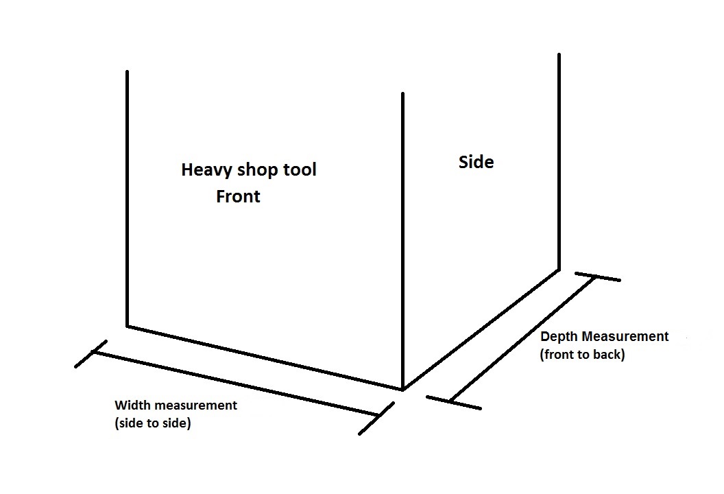
Measure the base of your shop tool. This is the bottom part of your shop tool that will sit on top of the mobile tool base. All we need here is the width (side to side) measurement and the depth (front to back) measurement and add an extra half inch to each of these measurements. Then add an extra 6-1/2 inches ONLY to your width measurement. Save these final measurements as the following steps will refer to the final measurements from this step.
STEP TWO:
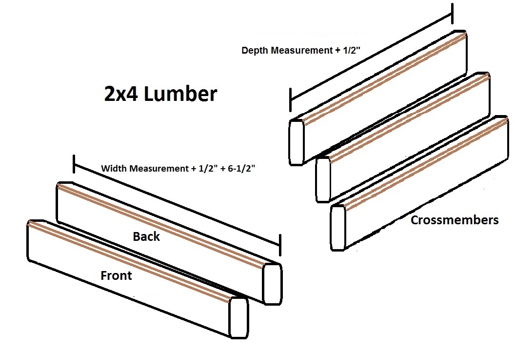
Make 2 identical cuts into 2×4 lumber with your width measurement from step one (these will be your front and back frame members) and make 3 identical cuts also using 2×4 lumber with your length measurement from step one (these will be your crossmembers).
STEP THREE:
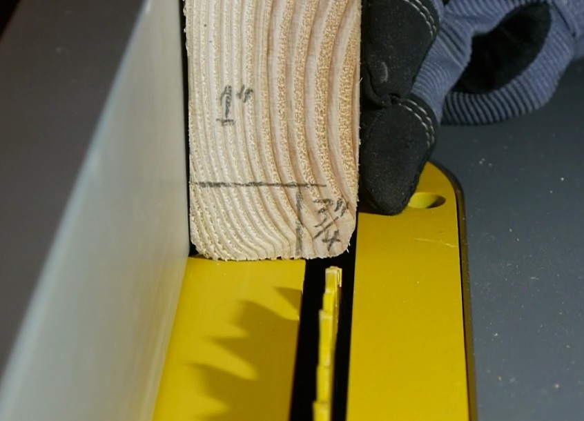
Make a 1 inch tall by 3/4 inch wide rabbet into both front and back frame members as shown below, and also make the same rabbet cut into ONLY ONE crossmember piece. Place these pieces aside for now.
STEP FOUR:
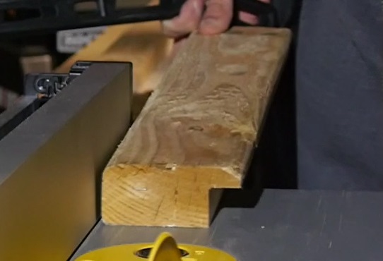
On another crossmember piece cut 3/4 inch off. This will leave this crossmember piece with a dimension of 1-1/2″ thick x 2-3/4″ tall. Place this piece aside for now.

STEP FIVE:
Using the final depth measurement from step one (the final length measurement is the original depth measurement plus 1/2″), add an extra 2 inches to this measurement. This will be the length of the plywood boards. Make the width of the boards about 6-1/2 inches and make 2 identical cuts into 3/4″ plywood.
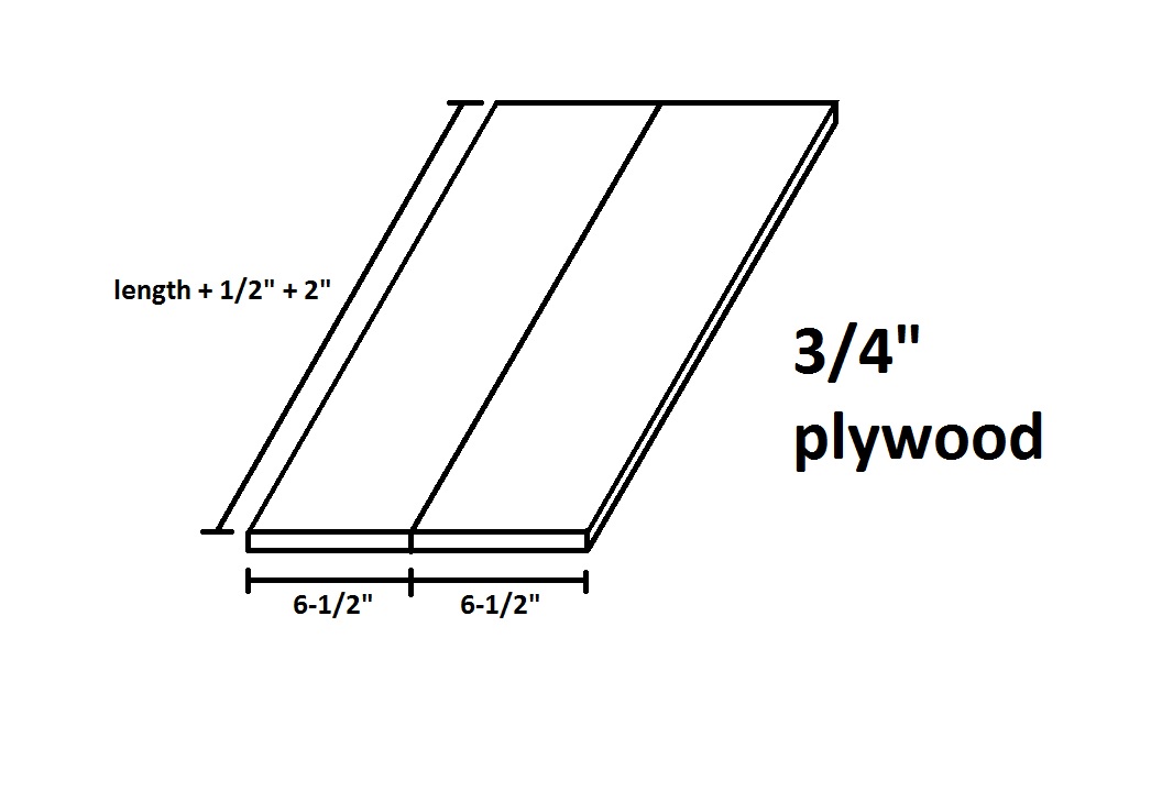
Now you should be left with 2 identical front and back frame members with rabbets, 1 crossmember piece with a rabbet, 1 crossmember piece with 3/4″ removed (this piece is from step four), one unmodified crossmember piece, and 2 plywood boards. These pieces make up the frame of the mobile tool base.
STEP SIX:
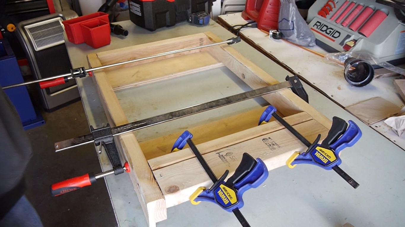
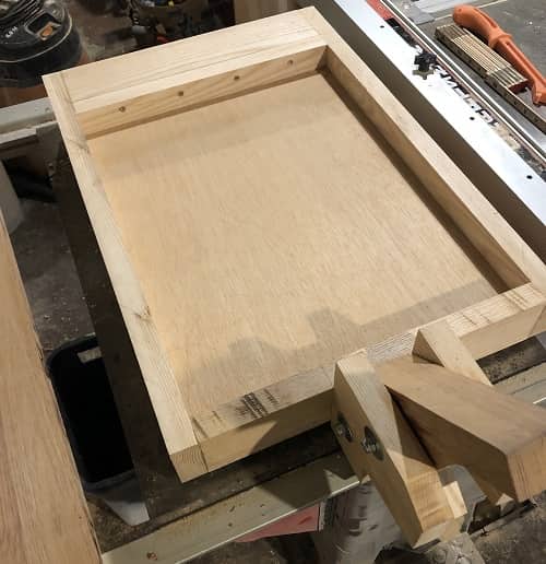
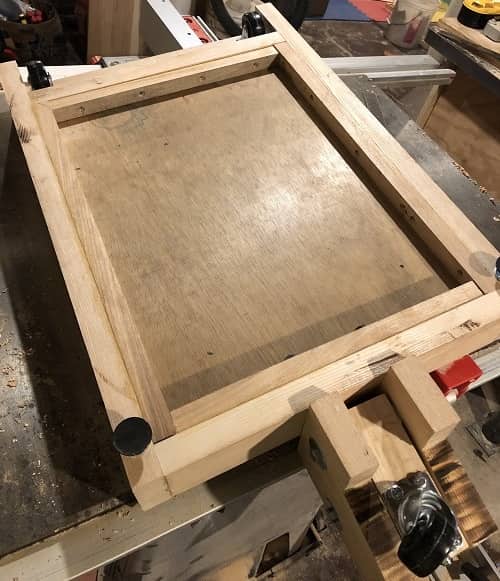
Now it’s time to assemble the base. Place the 2 plywood boards down and spread them apart. Place the crossmember piece from step 4 on the left side of left plywood board with the cut side facing down. Grab the 2 front and back frame members and place one in the front and place one in the back with the rabbet grooves sitting over the plywood planks. Then place the crossmember with the rabbet groove over the right side of the right plywood place with the rabbet groove sitting over the plywood. Then clamp down the left side and tighten. Then clamp down the right side but don’t tighten all the way, leave enough slack to allow the placement for the last crossmember. Then place the last crossmember on the right side of the frame touching the crossmember with the rabbet groove. Place this crossmember towards the top of the frame. I added a couple of clamps to clamp these 2 crossmembers and then tapped them in place with a hammer. Then tighten the right clamp down all the way.
When done correctly, the mobile tool base will have an opening the size of the base of your shop tool plus an extra half inch for wiggle room. Watch the included video if you need help in this step.
STEP SEVEN:
Using 3 inch #8 gold screws fasten all the crossmembers in place. On the front and back frame members, predrill 3 holes and drive 3 screws where each crossmember connects.

STEP EIGHT:
Flip over the mobile base and fasten both plywood boards into the frame with 2 inch #8 gold screws. Make sure to predrill before driving each screw.

STEP NINE:
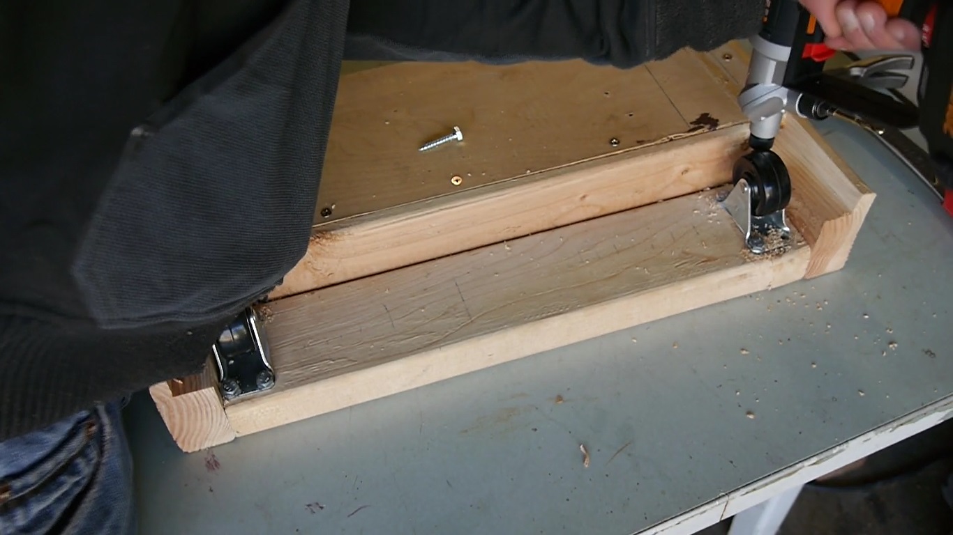
On the under side of the crossmember to the right, place the 2″ heavy duty fixed casters – one towards the front and one towards the back, each one facing with the wheels facing left and right. Pre-drill and drive four 1″ x 1/4″ lag screws to attach each caster.
STEP TEN:
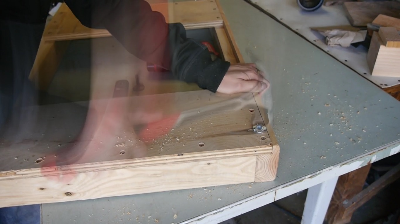
On the opposite side of the base (while the base is still upside down), using a 3/8″ drill bit, drill two holes 1-1/2 inch deep towards the end of the front and back of the frame. Then place the T-Nuts over these holes and hammer them into place. Then insert the elevator bolts by threading them in.
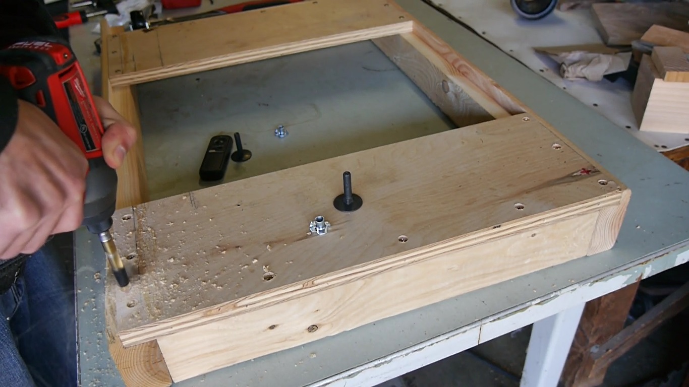
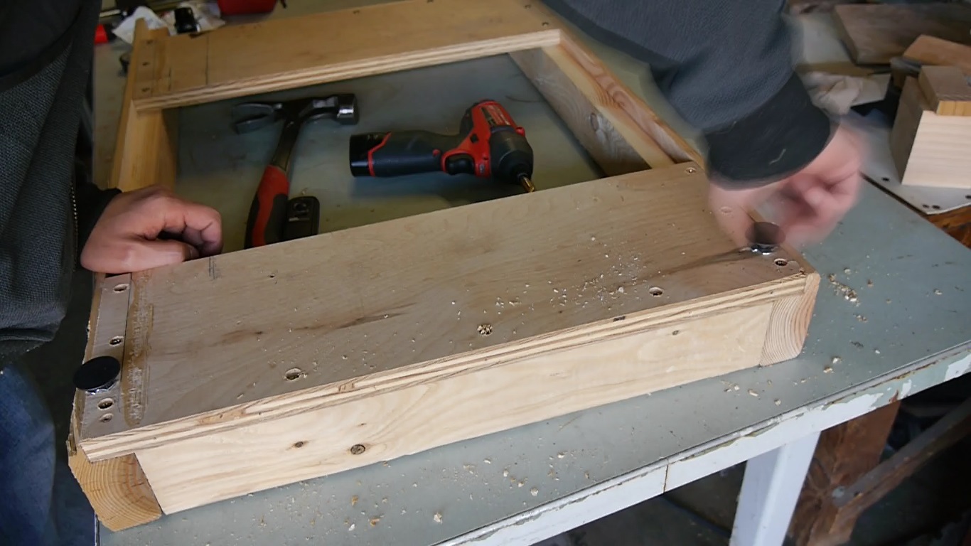
Flip over the mobile tool base and now the frame is completed. All it needs now is the lifting mechanism.
STEP ELEVEN:
Now we’re going to build the lifting mechanism. Grab your 2×6″ and make two cuts 6-1/8 inches wide. Grab your 4×6 or 4×4 and make one cut 9-1/4 inches wide, and grab a 2×4 and make a cut 5-3/4 inches wide. I know in the video I mentioned to use a 4×6 for the foot lever however a 4×6 is unnecessary for the project and all you need is a 4×4 instead.
STEP TWELVE:
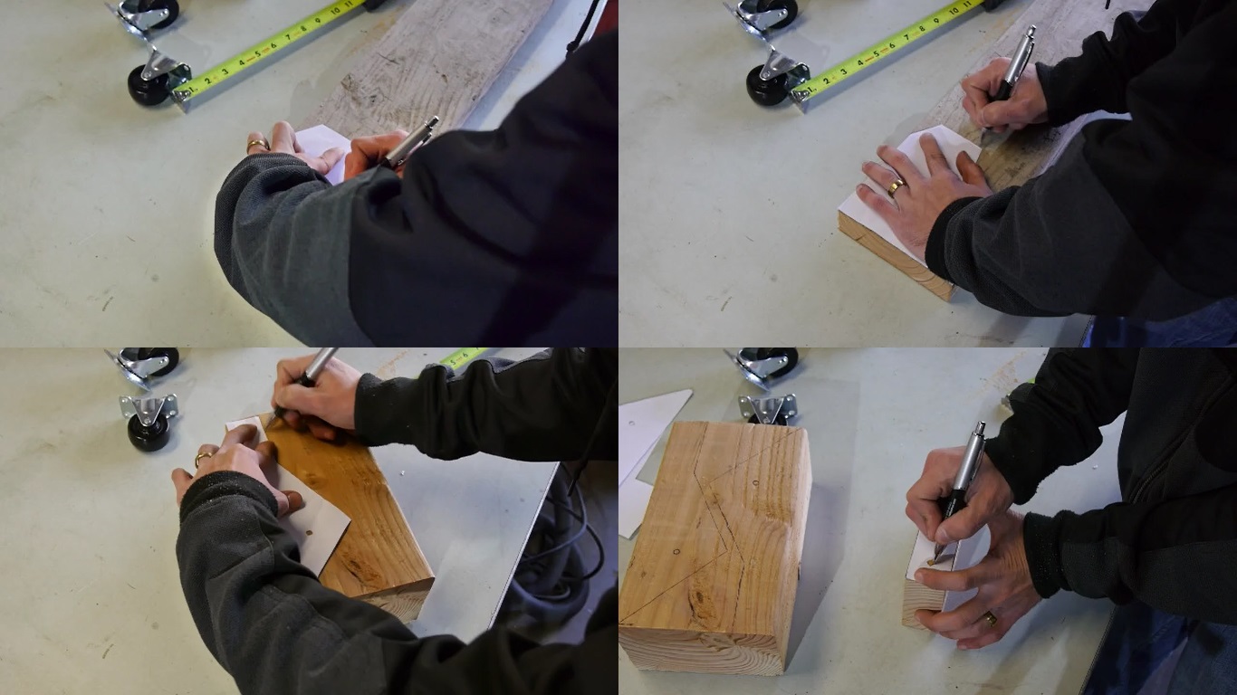
Download and print the templates used for this build and cut out each shape, including the holes. Then place the templates over the pieces you cut from step 11. The lifting mechanism side template goes over the two 2×6 cuts, the foot lever template goes over the 4×6, and the caster assembly template goes on the side of the 2×4. Trace the shape and mark the holes for the lifting mechanism side template and the foot lever template. Theres no need to trace the caster assembly template, this template is used to mark where to drill the hole, so mark where the hole is.
Click here to download templates
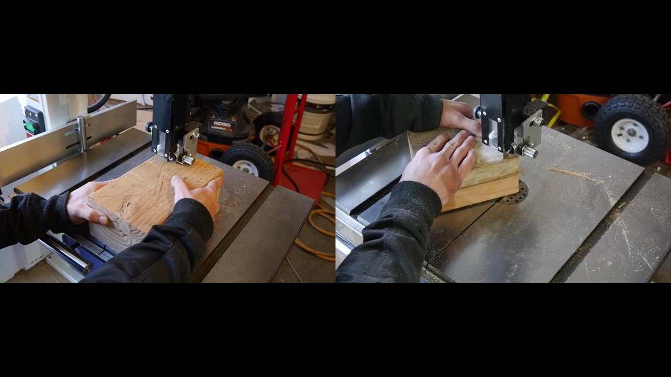
STEP THIRTEEN:
Cut out the shapes for the foot lever and lifting mechanism sides with your bandsaw.
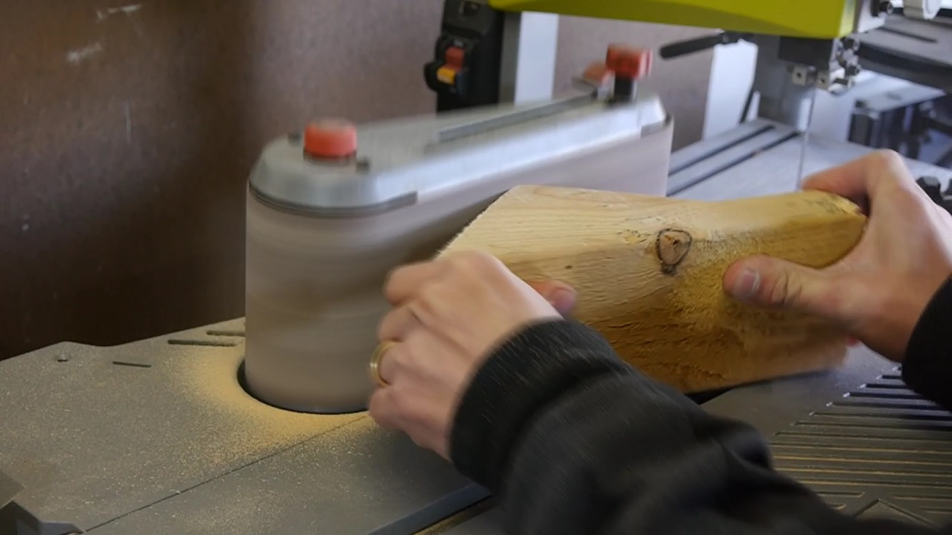
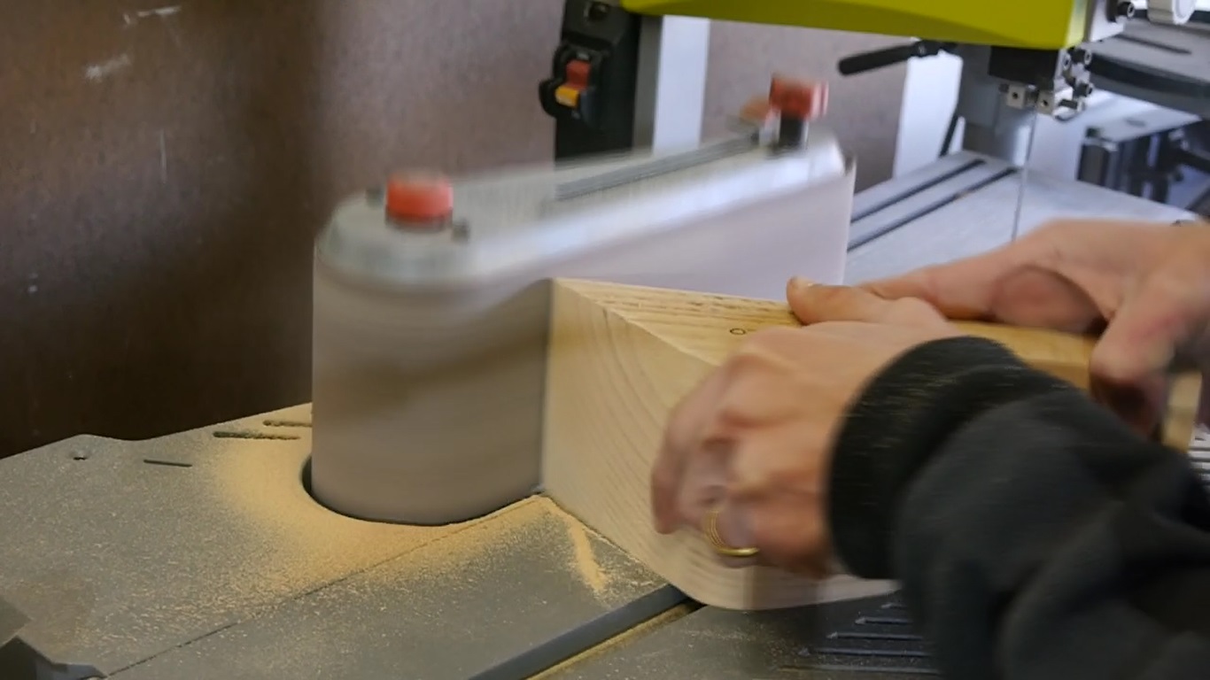
STEP FOURTEEN:
Take the foot lever to the belt sander and sand these two corners.
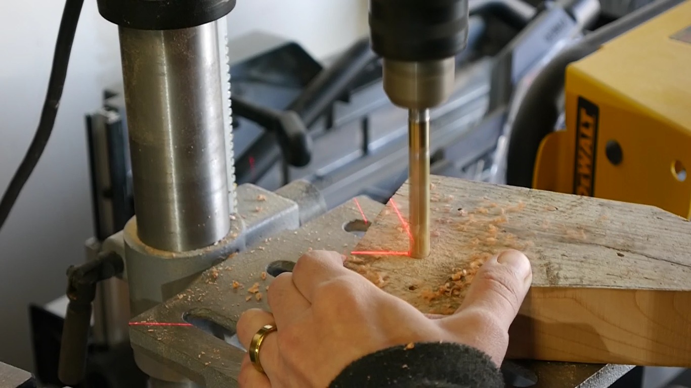
STEP FIFTEEN:
Using a 3/8″ drill bit, drill out each hole with your drill press.
STEP SIXTEEN:
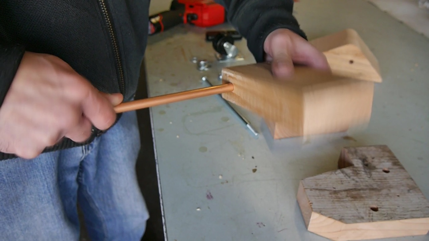
Insert the 1/4″ copper pipe into each hole you just drilled. The fit should be tight so be prepared to use some elbow grease. Cut the overhang of the pipe with a reciprocating saw equipped with a metal cutting blade.
STEP SEVENTEEN:
Grab some sheet metal and using some tin snips also called aviation snips, cut out 2 pieces. One piece will measure 3-1/4″ x 4-1/2″ and the longer piece will measure 3-1/4″ x 7-1/2″. Wear gloves and make sure not touch the edges of the cut sheet metal since it’s very sharp.

STEP EIGHTEEN:
Place the smaller sheet metal piece over the 2×4 that makes up the caster assembly. Place it on the end opposite of the side with the hole. Then clamp down and nail into place with 4 nails.

STEP NINETEEN:
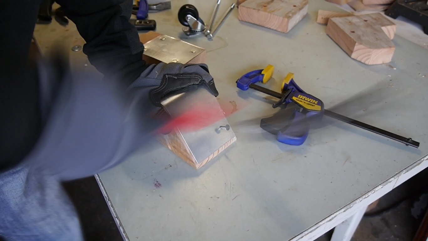
Place the larger sheet metal piece over the rounded part of the foot lever and bend it over the the bump. Remove the sheet to bend even further. Then place the bent sheet metal over the foot lever and nail into place with 4 nails.
STEP TWENTY:
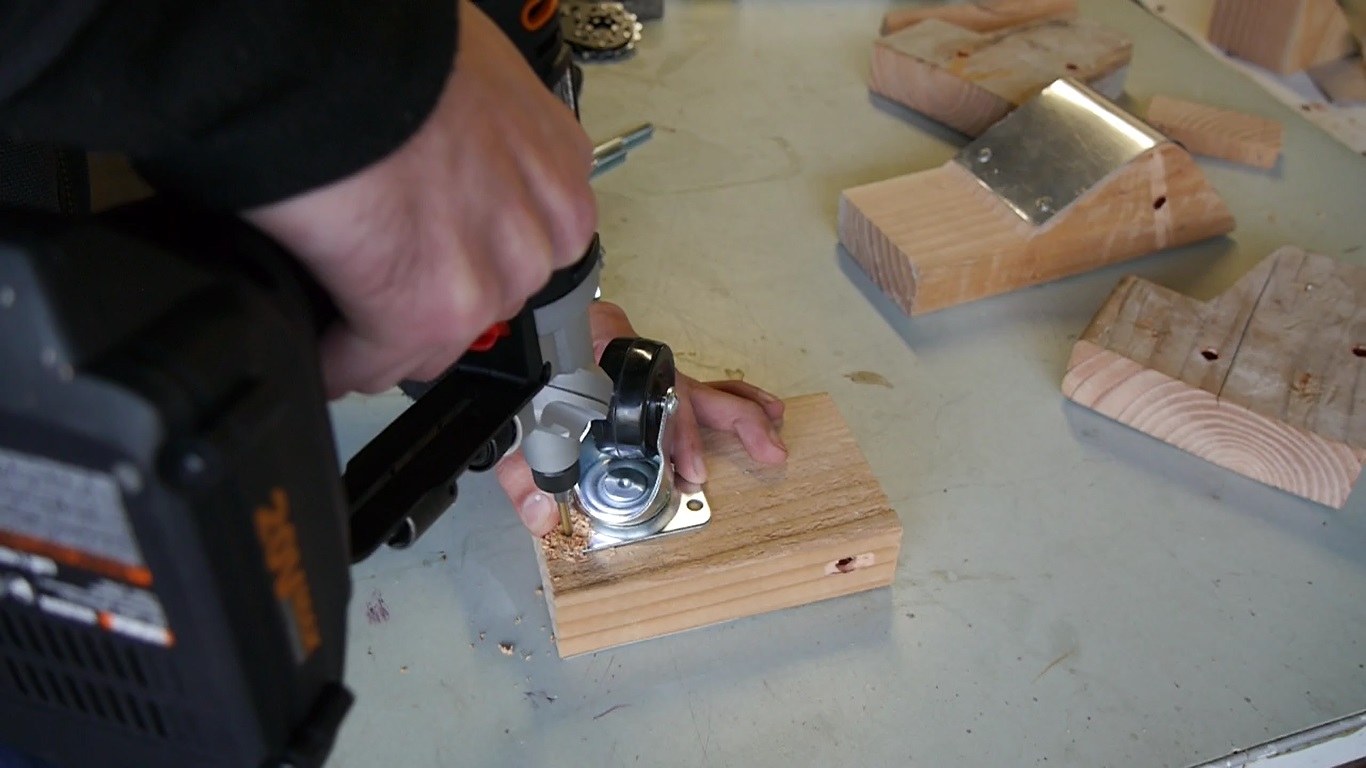
Grab the caster assembly, flip it over, and place the rotating caster on the end opposite of the hole. Attach this caster by predrilling and driving four 1″ long 1/4″ lag screws.
Now its time to assemble the lifting mechanism.
STEP TWENTY-ONE:
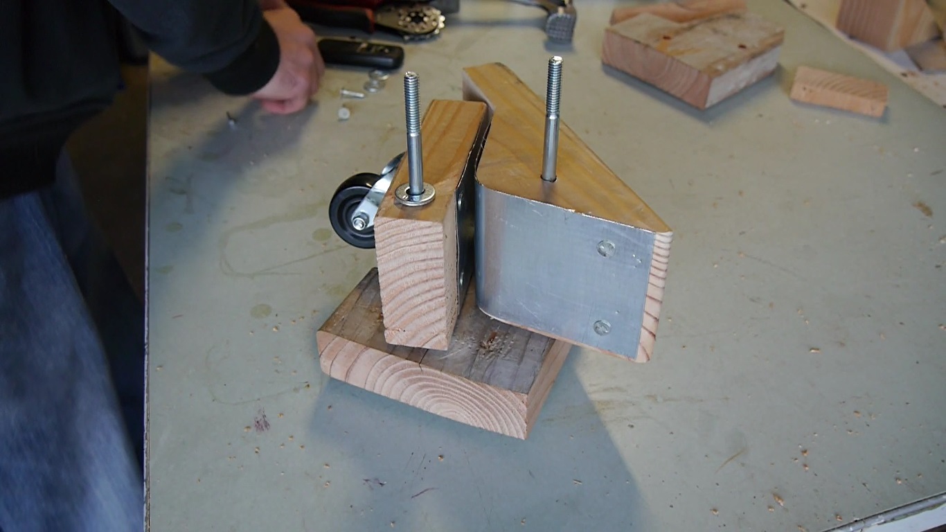
Grab the two 8 inch long 5/16″ lag bolts and insert one 5/16″ washer in each bolt. Then insert both bolts into the left side of one of the lifting mechanism side pieces (the piece cut out from 2×6) and place this piece down with the bolt heads underneath and the bolt threads facing up. Then insert two 5/16″ washers into each bolt, yes 2 washers for each bolt. Then slide the foot lever on the top bolt. Then slide the caster assembly on the bottom bolt. Next, insert another 2 washers over each bolt. Then place the right side of the lifting mechanism. Insert the last two 5/16″ washers, one in each bolt and then add the 5/16″ lock nuts over each bolt and tighten. Make sure to tighten everything snug but yet loose enough so the caster assembly and foot lever can move easily.
Next we need to attach the lifting mechanism onto the frame of the base.
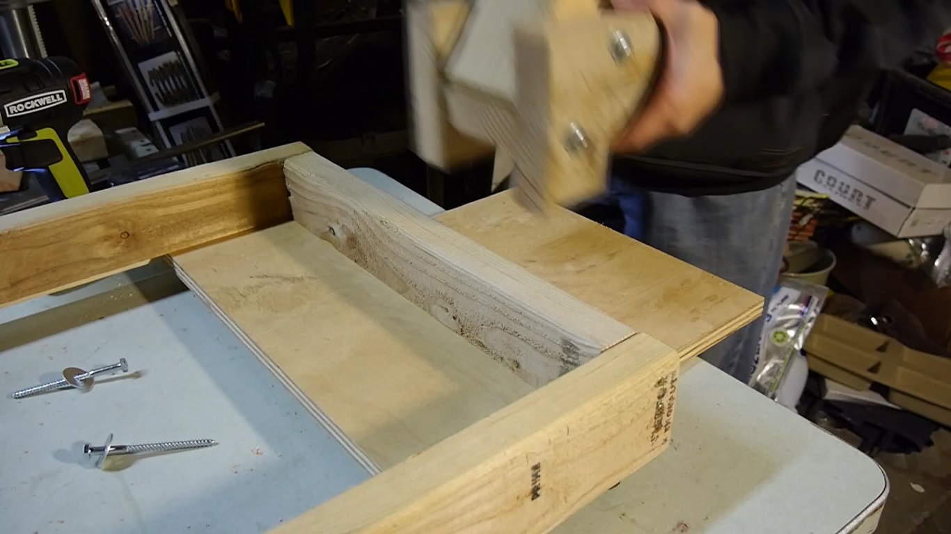
STEP TWENTY-TWO:
Place the lifting mechanism assembly on the opposite side of the fixed casters and it also must be in the center of the side of the frame. The bottom of the lifting mechanism must be flush with the bottom of the frame. To help with this, I used a scrap piece of plywood underneath both the frame and the lifting mechanism so both would be flush with each other.
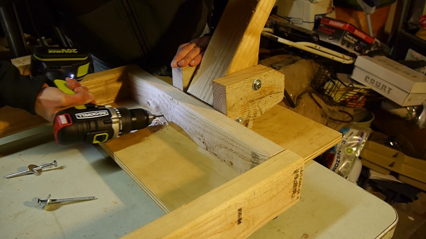
STEP TWENTY-THREE:
Attach the lifting mechanism to the mobile tool base frame with the 3-1/2″ long 1/4″ lag screws. Predrill and drive the first lag screw, then predrill the last 3 lag screws and drive them all in. A word of caution – make sure to avoid drilling into the bottom lag bolt. When drilling the bottom lag screws, drill each hole at a slight angle facing down, and the top two lag screws drill the holes a a slight angle facing up. This will help avoid running into the lag bolt.
Your mobile tool base is now complete! Test it out and make sure everything functions. The pressing down on the foot lever raises that side of the frame off the ground allowing the wheel to make contact and to be able to move around freely. Lifting the foot lever lowers the frame on the ground and rests on the elevator bolts and now can’t be moved around freely.

Once everything is done, mount your heavy shop tool on the base and adjust the elevator bolts so that the base is level when the frame resting on the floor.
Final thoughts:
So after building 2 sets of these mobile tool bases, I appreciate the ability to make my heavy bandsaw and jointer mobile. The larger 3 inch caster wheels on my jointer mobile tool base do run smoother and turns better although I’m not sure if this is due to the larger wheel size or because the jointer weighs considerably less than the bandsaw. Also on both mobile tool base’s I built, if you turn the units too sharply, the single wheel side tends to tip on occasion. You don’t have to worry about the actual tool tipping over since the the base sits very close to the ground and the side corners of the frame catch the floor preventing the tool from tipping over anyway. But this is only if you turn the base too sharply and quickly. It rides and turns good most of the time. I bring this up because if this will be an issue for your build, the easy solution is to build 2 lifting mechanisms and place them closer to the outside corners instead of one smack dab in the center.
If you end up building a mobile tool base based on this design, I would love to see it. Email me a picture and I’d love to post it below for all to see.
email: imcrazyabouttools@gmail.com
Images of completed mobile tool bases from others who’ve used these plans
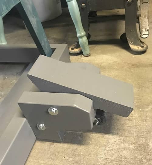
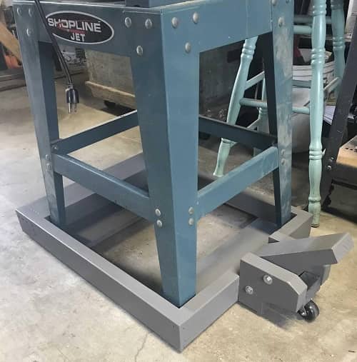
Chris’s October 2018 build for his Jet bandsaw – added a custom gray paint job.
His build appears to be an exact replica of my plans and it turned out great! Thank you for sharing!
What Chris had to say about his build experience:
Hi. My name is Chris and after looking at many mobile bases I could build for my new (to me) Jet JSL 12BS, I decided on yours. I liked your build process and the base design. I initially used small nails (too small) to affix the sheet metal parts to the lift mechanism. After two lifts, the sheet metal started to come off, so I took the lift apart and reattached it with countersunk drywall screws. Works great now. I got fancy pants and dimensioned my 2×4’s on the planer first and then sanded, rounded the edges, and primed and painted the whole build. The base works as advertised. If your plans had provided for larger casters, I would have used 3”, but my 2” heavy duty casters work fine.Thnx for the excellent design and plans!Chris


Jared A. L.’s August 2020 build for his 300 lbs mortising machine – built with hardwoods and custom mods. Says he will build more and one with two foot levers!
He customized his by ditching rabbet slots into the frame lumber which act as grooves for the plywood base and instead opted for 1×1 pieces that act as brace supports for the plywood bottom. This will add some extra height to the tool no doubt which may or may not be what he was looking for. I noticed the foot lever mechanism is sitting lower than the frame which should be flush with the bottom of the frame as mentioned in step twenty two. Hopefully his foot lever doesn’t touch the floor when parked otherwise he will have to adjust the leveling feet screws or just reattach the foot lever mechanism flush. He also used slightly larger 2.5″ casters which should help for easier rolling. Good job Jared and thanks for sharing!
What Jared had to say about his build experience:
Awesome plans. Built one with a couple mods. Used ash (frame), red oak (foot lever), and hard maple (1×1) scraps I had around the shop. Glued/screwed 1×1 on the inside of the frame flush with bottom and inserted plywood on top assuming that’ll carry the weight a little better (assumption). Loaded a Powermatic 719A Mortising machine, about 300 lbs, on it and no problems. Used 2.5″ casters. Total cost was under $30. I have a few more I need to build now and will try the 2 lever action as I mentioned in my post on your site.
Nice design- really worked well- thank you for sharing that out.Jared
If you end up building a mobile tool base based on this design, I would love to see it. Email me a picture and I’d love to post it below for all to see.
email: imcrazyabouttools@gmail.com
Thank you Javier, for a practical, fast, and efficient mobile base. I’m a musician who don’t have a lot of time to spent on making a quality stand. Your fit my needs perfectly. I have the wood and a little time and your design will last a life time. Thank you for sharing.
Note: I have found that 3in. wheels on mobile base units are easier for me to move and control. I will be installing 3″ high quality wheels using parts of your design. Thank you for everything. You have a well organized web page, keep up the great work.
[…] at first. However, Javier over at Tool Craze lays out the intricate steps for constructing a mobile tool base. The most difficult parts lay in organizing and placing the wood in the correct […]
That’s pretty smart! Simple is always better.
Javier- this is what I was looking for! Have you tried or heard of anyone trying to put two of the foot levers on the end/side with a board spanning both so they operate together? I’d like to add a 4th caster for weight and thinking about doing something like this, but am afraid if I operate them independently, I’ll have tipping problems.
I haven’t tried it but I did mention it in my final thoughts paragraph at the end of the article.
I’m getting ready to build two of these for my garage shop. I only have one question. You’re drilling 3/8′ holes in the foot lever mechanism. Then installing 1/4″ copper pipe in the holes. It will be a tight fit since the pipe is .375 OD and the holes have a .375 ID. My question is how do you now fit the 5/16″(.3125″) O.D. bolts in the 1/4″(.250″) I.D. copper pipe??? Am I missing something or is there a miss print??
I’m having difficulty obtaining the plans. Can someone furnish them to me,,,I am totally sold on the design/features etc. I’m willing to pay real $$$.
Desperate DIY’r.
Russ
August 24, 2023
No need to pay, my templates are free to download. Instructions are included.